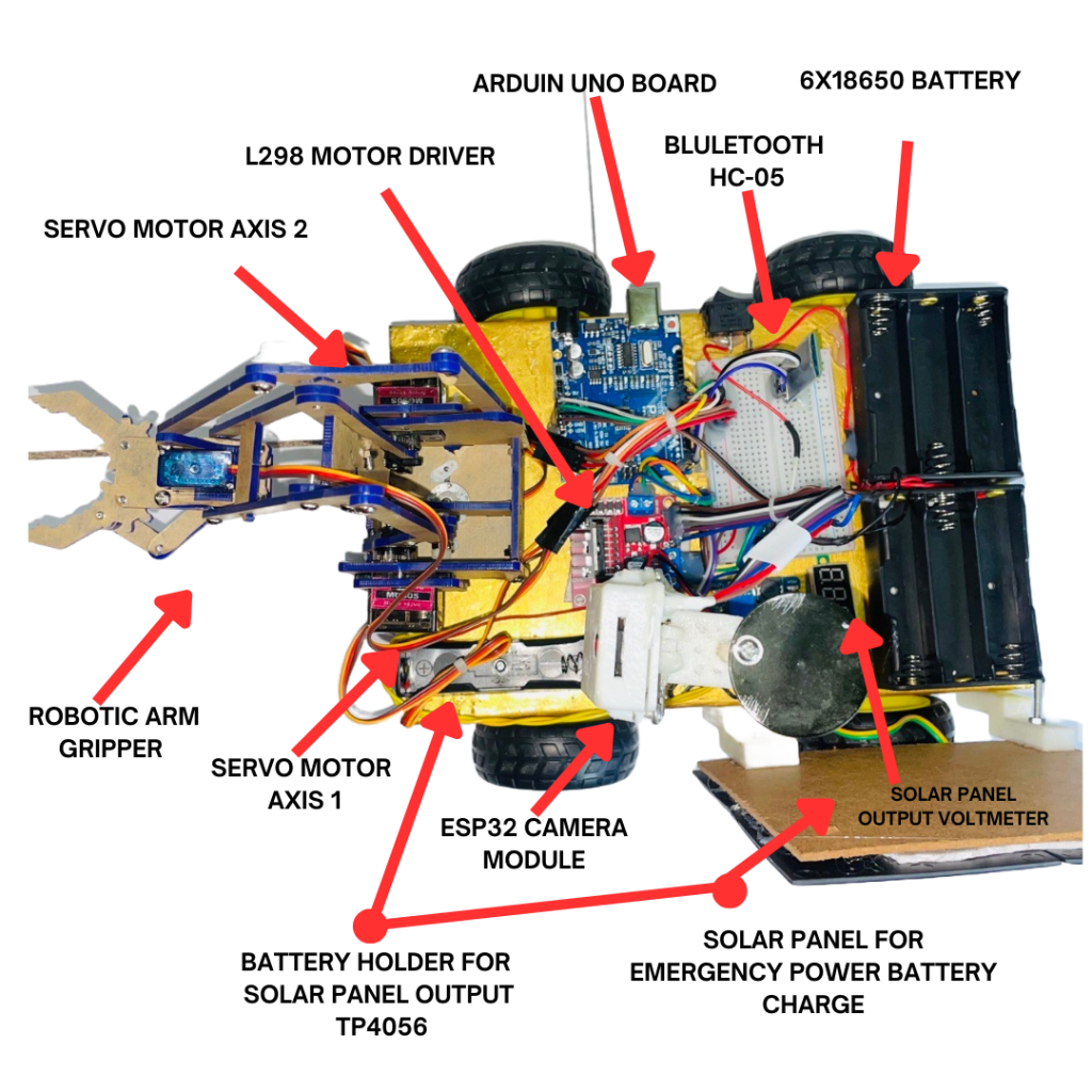
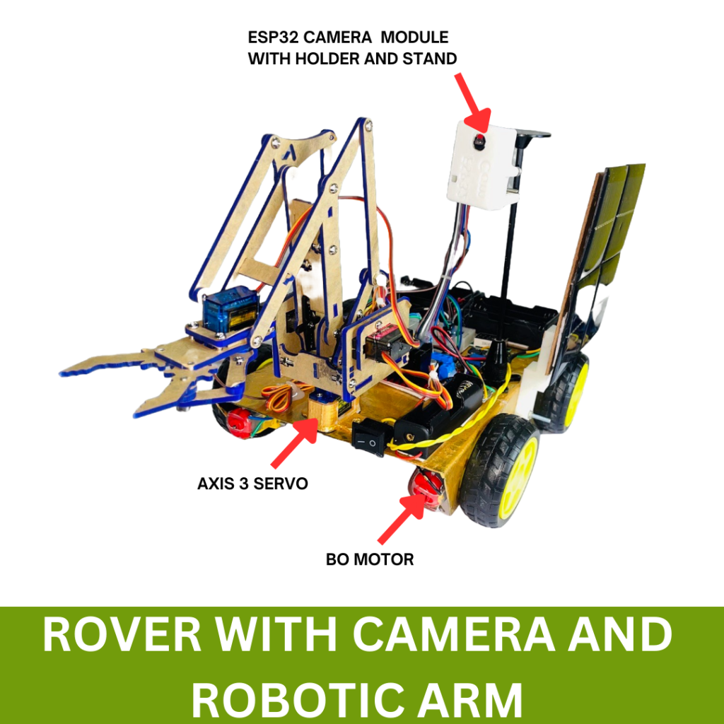
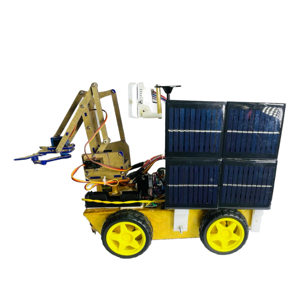
This tutorial will guide you through the process of building a 4-wheeler rover that features a mini robotic arm, an ESP32 camera module, and solar charging capabilities. Whether you’re a student working on a science exhibition project or an engineer looking for a hands-on learning experience, this project is perfect for you.

Materials Required
- 4 x BO Motors
- 1 x L298 Motor Driver Module
- 1 x Arduino Uno Microcontroller Board
- 1 x ESP32 Camera Module with Stand
- 1 x Bluetooth HC-05 Module
- 1 x Mini Robotic Arm Kit
- 6 x 18650 Li-Ion Batteries
- 1 x Solar Panel (suitable for charging Li-Ion batteries)
- 1 x Voltmeter LED Display
- Chassis for the 4-Wheeler Rover
- Wires, Connectors, and Soldering Kit
- Breadboard and Jumper Wires
- Screws, Nuts, and Tools for Assembly
Step 1: Assembling the Rover Chassis
Attach the Motors
- Secure the four BO motors to the chassis using screws and nuts.
- Ensure the motors are aligned correctly for smooth movement.
Wire the Motors to the L298 Motor Driver
- Connect the BO motors to the L298 motor driver module.
- Connect the two motors on the left side to one channel and the two on the right to the other channel.
- Use jumper wires to make connections from the IN1, IN2, IN3, and IN4 pins on the motor driver to the Arduino.
Power the Motors
- Connect the motor driver’s power input (VCC) and ground (GND) to the 6 Li-Ion batteries.
- Ensure the batteries are wired in series to provide adequate voltage.
Step 2: Setting Up the Arduino Uno
Connect the Motor Driver to the Arduino
- Connect the IN1, IN2, IN3, and IN4 pins from the motor driver to digital pins on the Arduino Uno (e.g., pins 8, 9, 10, and 11).
- Connect the ENA and ENB pins of the motor driver to PWM-capable pins on the Arduino (e.g., pins 5 and 6) for speed control.
Power the Arduino
- Connect the Arduino to the battery pack’s output, or use an external power source.
- Ensure the ground from the battery pack is connected to the Arduino’s GND.
Step 3: Installing the Robotic Arm

Assemble the Mini Robotic Arm
- Follow the instructions provided with the robotic arm kit to assemble the arm.
- Attach the arm to the front of the rover’s chassis using screws or a custom mount.
Connect the Arm to the Arduino
- Connect the servo motor of the robotic arm to the PWM pins on the Arduino (e.g., pins 3, 4, and 5).
- You may need to power the servos using a separate 5V power supply, depending on their current draw.
Step 4: Setting Up the ESP32 Camera Module

Mount the ESP32 Camera
- Secure the ESP32 camera module on a stand and attach it to the rover’s chassis.
- Ensure the camera has a clear field of view for live streaming.
Connect the ESP32 to the Arduino
- Power the ESP32 module using the same battery pack or an external 5V supply.
- Upload a simple camera streaming code to the ESP32 using the Arduino IDE.
Step 5: Adding the Bluetooth HC-05 Module
Connect the Bluetooth Module
- Wire the HC-05 module to the Arduino Uno: TX to RX (pin 0), RX to TX (pin 1), VCC to 5V, and GND to GND.
- The HC-05 allows wireless control of the robotic arm via Bluetooth.
Pair the Module with an Android Device
- Use the provided Bluetooth app to pair the HC-05 module with your Android phone.
- Customize the app to control the robotic arm servos.
Step 6: Implementing Solar Charging
Connect the Solar Panel
- Attach the solar panel to the rover’s chassis where it will receive maximum sunlight.
- Wire the solar panel output to the battery pack via a charge controller to prevent overcharging.
Install the Voltmeter Display
- Connect the voltmeter LED display between the solar panel and battery pack to monitor the input voltage.
- Mount the display on the rover’s chassis for easy visibility.
Step 7: Programming the Arduino
Upload the Control Code
- Write or upload the Arduino code to control the rover’s movement, robotic arm, and Bluetooth commands.
- Include functions for forward, backward, left, and right movements, as well as arm manipulation.
Test the Functionality
- Once the code is uploaded, test all the rover’s functions: motor control, robotic arm movement, and camera streaming.
Step 8: Final Assembly and Testing
Assemble All Components
- Ensure all components are securely mounted and connected.
- Double-check wiring for any loose connections or shorts.
Test the Rover
- Power up the rover and test each feature individually.
- Fine-tune the code or hardware connections if needed.
Step 9: Customizing and Enhancing the Rover
Now that you have completed the basic build, you can explore various ways to customize and enhance your rover project. Here are some ideas:
- Add Sensors for Autonomous Navigation:
- Install ultrasonic sensors for obstacle detection and avoidance.
- Connect the sensors to the Arduino and update your code for autonomous movement.
- Implement GPS for Location Tracking:
- Integrate a GPS module with the Arduino to track the rover’s location.
- Use this feature to map the rover’s movements or implement waypoint navigation.
- Upgrade the Camera:
- Consider upgrading the ESP32 camera module for higher resolution or low-light performance.
- Add a second camera for a different viewing angle or stereoscopic vision.
- Enhance the Power System:
- Increase battery capacity by adding more Li-Ion cells or switching to higher capacity batteries.
- Integrate a more sophisticated solar charging controller for better energy management.
- Create a More Advanced Control App:
- Develop a more complex Android app with additional features like autonomous mode or voice control.
- Add data logging for monitoring sensor inputs, battery levels, and camera feed.
- Integrate Artificial Intelligence (AI):
- Use machine learning techniques for object recognition or advanced decision-making.
- This can be useful for complex environments like search and rescue missions.
- Improve the Rover’s Mobility:
- Upgrade the wheels to more robust, all-terrain types for rough terrains.
- Add a suspension system for better stability and handling on uneven surfaces.
- Include a Display for Real-Time Data:
- Mount an LCD or OLED display on the rover to show real-time data like speed, battery level, sensor readings, or GPS coordinates.
- This display can be useful for live demonstrations.
- Add Communication Features:
- Integrate a long-range communication module like LoRa for remote operation over greater distances.
- Add a GSM module for cellular communication, allowing control from anywhere.
- Waterproof the Rover:
- Waterproof the electronics and motors if you plan to use the rover outdoors.
- Use waterproof enclosures, sealant, and specialized connectors.
Step 10: Documenting and Sharing Your Project
- Create Detailed Documentation:
- Document each step of the build process, including wiring diagrams, code explanations, and assembly instructions.
- This documentation is invaluable for replicating or troubleshooting the project in the future.
- Share Your Project Online:
- Share your project on platforms like GitHub, Instructables, or Hackster.io.
- Include photos, videos, and a complete parts list for others to follow your guide.
- Engage with the Community:
- Join online forums or social media groups related to robotics, Arduino, or DIY electronics to share your progress, get feedback, and collaborate with others.
- Consider entering your project into competitions or exhibitions.
Conclusion
Your 4-wheeler rover with a robotic arm, ESP32 camera, and solar charging is now complete! This project is an excellent way to learn about robotics, microcontrollers, and renewable energy applications. Whether for educational purposes or as a hobby, this project offers a hands-on experience with endless possibilities for customization and enhancement.

Leave a Reply