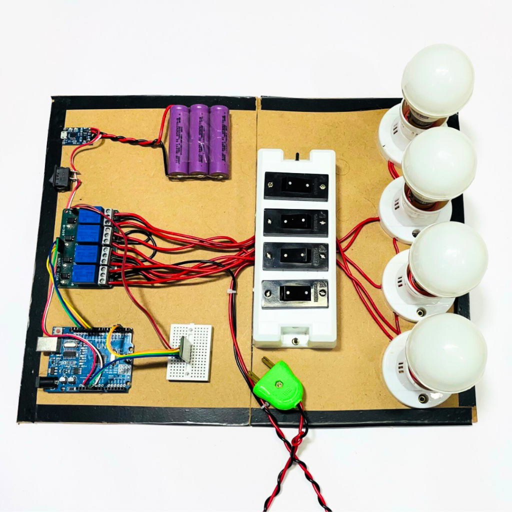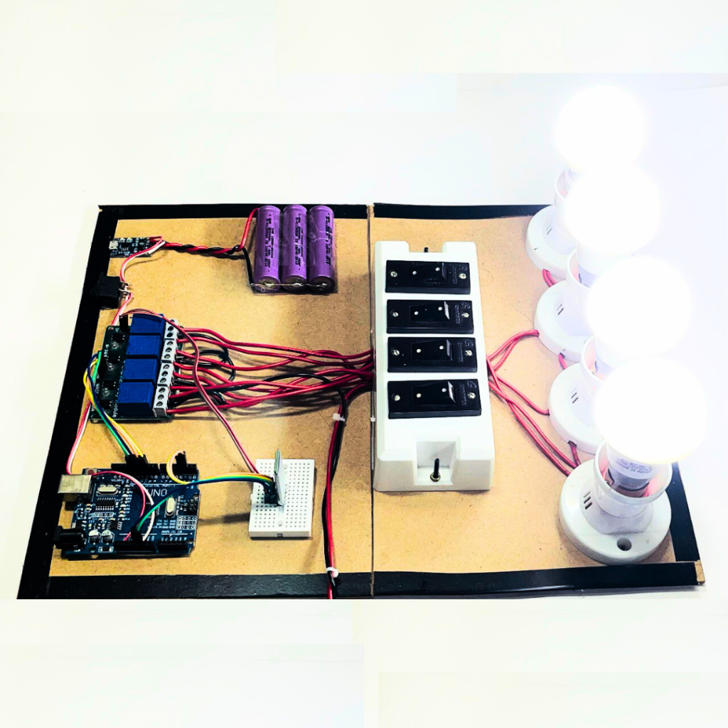
In this tutorial, we’ll walk you through how to build a 4-Channel Bluetooth-controlled home automation system. You will use an Arduino-compatible board, HC-05 Bluetooth module, and 4-channel relay to control four different devices, such as LED bulbs. This project is ideal for engineering or science exhibitions, or for those who want to get started with home automation and Engineering Final Year.
Materials Required:
- HC-05 Bluetooth Module
- 4-Channel Relay Module
- Arduino Uno-compatible board
- 4 LED Bulbs with Holders
- 4 Two-way Switches
- Breadboard
- Jumper Wires
- 3 Li-ion Batteries (18650)
- TP4056 Charging Module
- Switch
- MDF Board for mounting components
- USB Cable for Arduino
- Android Phone for Bluetooth control app
- Power supply for Arduino (via USB or battery)
Step-by-Step Instructions

Step 1: Preparing the Components
- Arduino Uno-compatible board: This will be the brain of your system. It will control the relay and communicate with the HC-05 module.
- HC-05 Bluetooth Module: This allows wireless communication between your smartphone and the Arduino to send commands.
- 4-Channel Relay Module: It enables switching of high-power devices like LED bulbs.
- TP4056 Charging Module: It will charge the 3 Li-ion batteries, powering the system.
Step 2: Wiring the Circuit
- HC-05 Bluetooth Module:
- Connect VCC of the HC-05 to 5V on the Arduino.
- Connect GND of the HC-05 to GND on the Arduino.
- Connect TXD of the HC-05 to RX on the Arduino (Pin 0).
- Connect RXD of the HC-05 to TX on the Arduino (Pin 1).
- 4-Channel Relay Module:
- Connect the IN1, IN2, IN3, and IN4 pins of the relay to Pins 2, 3, 4, and 5 on the Arduino.
- Connect VCC and GND of the relay module to the 5V and GND pins of the Arduino.
- LED Bulbs:
- Connect each LED bulb holder to the NO (Normally Open) contacts of the relay module.
- The other end of the bulbs will be connected to the 2-way switches for manual control.
- Switch Wiring:
- Wire the two-way switches in parallel with the relay, so you can control each bulb either with Bluetooth or with the switch manually.
- Power Supply Setup:
- Connect the 3 Li-ion batteries to the TP4056 charging module for recharging.
- Wire the batteries to power the relay module and the Arduino through the Vin pin on the Arduino (you can also use the USB port for external power).
Step 3: Coding the Arduino
- Arduino IDE Setup: Download and install the Arduino IDE from the official website. Ensure the correct board (Arduino Uno) and COM port are selected.
- Bluetooth Control Code: Write or upload the following code to the Arduino.
#include <SoftwareSerial.h>

SoftwareSerial BTSerial(0, 1); // RX, TX

int relay1 = 2;
int relay2 = 3;
int relay3 = 4;
int relay4 = 5;

void setup() {
  pinMode(relay1, OUTPUT);
  pinMode(relay2, OUTPUT);
  pinMode(relay3, OUTPUT);
  pinMode(relay4, OUTPUT);

  digitalWrite(relay1, HIGH); // Relays off
  digitalWrite(relay2, HIGH);
  digitalWrite(relay3, HIGH);
  digitalWrite(relay4, HIGH);

  BTSerial.begin(9600); // Start Bluetooth communication
}

void loop() {
  if (BTSerial.available()) {
    char data = BTSerial.read();

    // Control Relay 1
    if (data == '1') {
      digitalWrite(relay1, LOW); // Turn ON Relay 1
    } else if (data == '2') {
      digitalWrite(relay1, HIGH); // Turn OFF Relay 1
    }

    // Control Relay 2
    if (data == '3') {
      digitalWrite(relay2, LOW); // Turn ON Relay 2
    } else if (data == '4') {
      digitalWrite(relay2, HIGH); // Turn OFF Relay 2
    }

    // Control Relay 3
    if (data == '5') {
      digitalWrite(relay3, LOW); // Turn ON Relay 3
    } else if (data == '6') {
      digitalWrite(relay3, HIGH); // Turn OFF Relay 3
    }

    // Control Relay 4
    if (data == '7') {
      digitalWrite(relay4, LOW); // Turn ON Relay 4
    } else if (data == '8') {
      digitalWrite(relay4, HIGH); // Turn OFF Relay 4
    }
  }
}
- Upload the Code: Connect the Arduino to your computer using the USB cable and upload the code.
Step 4: Building the Android App
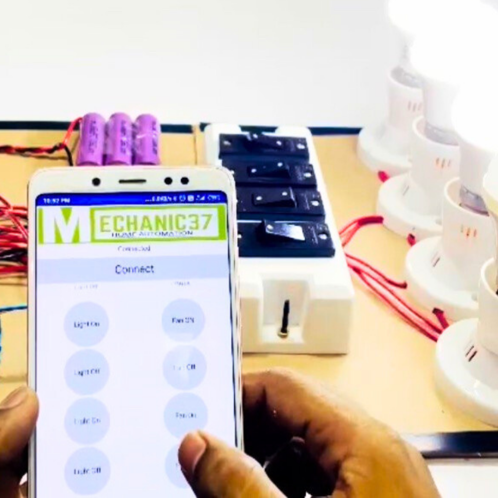
You can use any Bluetooth terminal app from the Play Store or create your own app using MIT App Inventor for a custom interface. Send the following commands from the app to control the relays:
- ‘1’ to turn ON Relay 1
- ‘2’ to turn OFF Relay 1
- ‘3’ to turn ON Relay 2
- ‘4’ to turn OFF Relay 2
- ‘5’ to turn ON Relay 3
- ‘6’ to turn OFF Relay 3
- ‘7’ to turn ON Relay 4
- ‘8’ to turn OFF Relay 4
Step 5: Assembling the Components on MDF Board
- Arrange the components neatly on the MDF board.
- Secure the Arduino, relay module, switches, breadboard, and batteries using screws or double-sided tape.
- Connect all wires and components as per the wiring diagram.
- Ensure all connections are firm and the system is ready for testing.
Step 6: Testing the System

- Power the system using the Li-ion batteries or USB power.
- Open the Bluetooth app on your Android phone and pair it with the HC-05 module (default pairing code is usually “1234” or “0000”).
- Test each relay by sending the respective commands from the app. The corresponding LED bulbs should turn on/off.
- Toggle the two-way switches to manually control the LEDs.
Conclusion:
Your 4-Channel Bluetooth Home Automation System is now complete! You can easily control your home devices wirelessly using your phone and Bluetooth or manually using switches. This project is a great way to learn about wireless communication, Arduino, and relay systems, making it an ideal choice for engineering and science exhibitions.

Leave a Reply